Extract airfoil coordinates from any image
Found a great airfoil in a paper or photo but can't find its coordinates? Upload any image or PDF, trace the shape with control points, and export clean .dat or .csv coordinates: the easy way to unlock airfoils that aren't in the UIUC database and use them across the design and simulation tools.
When you need to digitize an airfoil
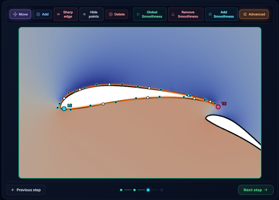
You see the perfect profile in a research paper, an old textbook, a competitor's photo or a manufacturer's brochure, but there is no coordinate file to go with it. Without coordinates you can't model it, mesh it or simulate it. The shape is right there, and completely out of reach.
The usual answers are bad ones: hand-measure points off a printout, settle for a different airfoil, or pay for a desktop digitizer and install it. The Airfoil Reader makes it a five-minute job in the browser: turn a picture into usable coordinates and carry on designing.
What is an airfoil .dat file? (Selig vs Lednicer)
An airfoil .dat file is just the profile written as a list of x/y coordinates, normalised so the chord runs from 0 to 1. Almost every aero tool reads it. There are two common orderings. The Airfoil Reader reads both when you import a file, and exports the Selig ordering, the de-facto standard that every aero tool understands.
One continuous loop: trailing edge → over the top → leading edge → under the bottom → back to the trailing edge.
MY-AIRFOIL
 1.00000  0.00000   # TE
 0.50000  0.05800
 0.00000  0.00000   # LE
 0.50000 -0.02100
 1.00000  0.00000   # TE
Two surfaces written separately: a point count, then the upper surface LE → TE, then the lower surface LE → TE.
MY-AIRFOIL
   3.   3.            # point counts

 0.00000  0.00000   # upper LE→TE
 0.50000  0.05800
 1.00000  0.00000

 0.00000  0.00000   # lower LE→TE
 0.50000 -0.02100
 1.00000  0.00000
Same geometry, two packagings. If you only ever needed the raw numbers (for a spreadsheet or a script), export plain .csv instead.
How to trace an airfoil from an image
A guided wizard walks you from a raw picture to clean coordinates. No measuring by hand, no desktop install.
-
1
Upload your image or PDFA screenshot from a paper, a scan, or a photo: anything that shows the profile clearly.Upload
-
2
Orient & scaleLine the profile up to the chord so coordinates come out normalised. The leading and trailing edges are detected for you.Orient
-
3
Trace the outlineDrop control points along the surface and drag them onto the shape. Add, move or delete points until the curve fits.Trace
-
4
Refine & smoothClean the traced curve so the surface is smooth and kink-free, ready for analysis.Refine
-
5
Export or saveExport .dat or .csv, or save the airfoil to your library for the design and simulation tools.Export
From a photo to clean coordinates
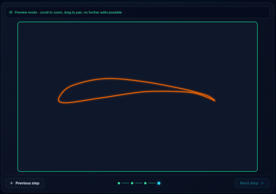
The traced profile becomes a smooth, normalised curve, the same kind of clean geometry you'd get from a published coordinate file, recovered from nothing but a picture.
From there it's yours to keep: download it as .dat or .csv, or save it to your on-site airfoil library so it's a click away the next time you design a wing or run an analysis. One traced profile, ready for every tool.
Use your airfoil in Wing Designer, XFOIL & CFD
The Airfoil Reader isn't a dead-end exporter: it feeds the rest of the toolchain. A profile you trace is immediately usable everywhere else, with no re-importing.
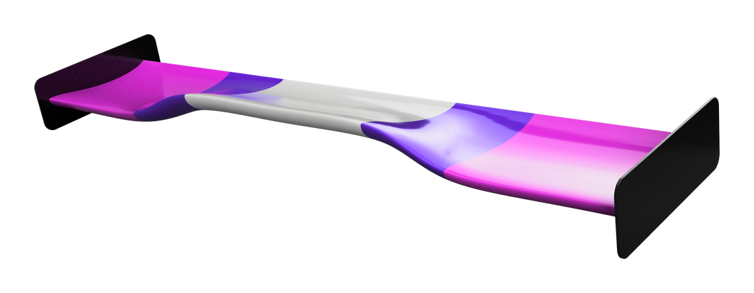
Build a wing around it in the Wing Designer, screen it with a fast polar in XFOIL, or send it to CFD for the full flow field. The airfoil you found in a paper this morning can be a simulated, manufacturable wing by the afternoon.
Airfoils beyond the UIUC database
The UIUC database is the go-to public collection, with coordinates for roughly 1,650 airfoils, but plenty of profiles never make it in: proprietary sections, niche research airfoils, older designs, and shapes published only as a figure. The Airfoil Reader is how you get those. If you can see it, you can trace it, and turn the whole world of printed airfoils into files you can actually use.
Built for Formula Student, FSAE & hobbyists
Formula Student and FSAE teams recover the exact profiles cited in papers and references so their design reports stand on real geometry, not a near-enough substitute. Motorsport hobbyists and track-day builders copy a wing section they admire and make it their own. Engineering students and researchers digitize airfoils from the literature to study, compare and simulate, pulling shapes out of figures and into tools that can actually analyse them. And since traced profiles work in both downforce and lift orientations downstream, aviation and RC builders can recover a wing section for an aircraft just as easily as for a race car.
Frequently asked questions
How do I get coordinates from an airfoil picture?
What file formats can I export?
What's the difference between .dat and .csv?
Can I use a scanned PDF?
Is it free?
Can I analyze the airfoil I traced?
How accurate is the tracing?
Keep going
Turn any airfoil image into coordinates
Upload, trace, export. Free and unlimited, right in your browser. Then design and simulate with what you traced.